
How to disassemble and reassemble a Nikon AF 20mm 1:2.8D lens in order to clean sticky aperture blades
This lens, along with the AF 35mm 1:2.0D and the AF Micro 55mm 1:2.8, is more prone to develop oil residue on the aperture blades than other lenses. Most lenses can develop this problem, but these three lenses (as far as I know) are the most problematic in Nikon’s line of lenses. The oil originates from the grease used to lubricate the focusing mechanism and if the lens is subjected to excessive heat or stored with the rear facing down then the oil works its way onto the blades which make them stick. Once the oil is on the blades, the aperture can be slow to close which causes overexposed images or the blades will not close at all which means you can only shoot properly exposed images wide open (maximum aperture). And sometimes the blades become oily even if the lens is properly stored. This means Nikon’s design and/or production methods are substandard for these lenses.
My 35mm 1:2.0D developed this problem in 1999 after only a couple of years. I sent it in for repair and it came back with clean blades and worked for a little while but developed the problem again and was sent in again. I think the cost was a little over $100. Now the lens is again developing the oily residue although I haven’t had any symptoms yet. But, it’s just a matter of time. You can read my original post on Photo.net here: http://photo.net/bboard/q-and-a-fetch-msg?msg_id=000isF.
And just recently my 20mm developed the same problem which is where we are at now. I took a photo with the lens and noticed it was extremely overexposed. I pressed the Depth of Field preview button (DOF) and nothing happened (the viewfinder should darken as the aperture stops down). I pulled then lens off and noticed the lens stayed wide open at f/22. The aperture lever had no effect.
I didn’t want to waste my time or money with having the lens “repaired” by Nikon or a service center since the problem would most likely return. Plus, I’m probably going to be buying a Nikon 14-24mm AFS f/2.8 G ED in the near future (donations graciously accepted) which would relegate the prime 20mm lens to back-up duty. So, I thought I would attempt to fix this myself and donate this lens to my edification. And for those of you eager to express your righteous indignation about taking apart a lens…spare me. It’s my lens.
The Internet was not much help. I could not find any diagrams or instructions on how to disassemble a newer Nikon lens. The only information I found was a diagram of two older Nikon manual focus non-AI 50mm lenses: http://rick_oleson.tripod.com/index-102.html. So, I thought I would blaze the trail myself.
It took me about two hours to get the lens all apart and about three hours to put it back together. I took it apart again and it only took about 10 minutes for disassembly and about 15 minutes for assembly then second time. So, you can see the learning curve is steep. The first disassembly took so long because of a stripped out screw plus I had no idea what I was doing.
And now for the disclaimer: Nothing is more expensive than free. This is free advice which you have found on the Internet. You use these instructions at your own risk. I’m not a lens expert nor do I suggest you try to fix your own lenses. I will not be held responsible for your stupidity or inadequacies. If you ruin your lens attempting this procedure then you got exactly what you deserve.
As for tools, you will need a good Phillips size 0x4. Don’t use those ubiquitous, cheap Chinese jewelers screwdrivers…they won’t cut it. I used a General brand #702 (Made in
A note on nomenclature: I don’t know the correct terms for many of these parts so I made up names which sound descriptive. If you know the correct name, let me know and I’ll update the information. Also, everything unscrews counter-clockwise. Remember: righty-tighty, lefty-loosey.
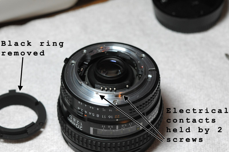
Let’s get started. This is the back of the lens. Remove the black inner ring which has three screws holding it. You can also see the three larger screws which hold the silver colored metal lens lock ring. The lower left screw ended up stripping on me and I had to drill out the head. All these screw are very tight and have some sort of thread locking material on them (like Loctite). Even when I was being careful, one of the screws stripped out on me. So, be careful. You can also see the slotted AF drive mechanism. If you manually turn the focusing ring, you will see this spin.
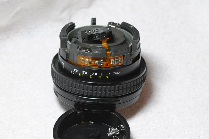
Once the black inner ring is removed, you can loosen the two very small screws that hold the electrical contact plate on the silver ring. The electrical contact plate has a ribbon cable attached which will keep it tethered to the main body of the lens.
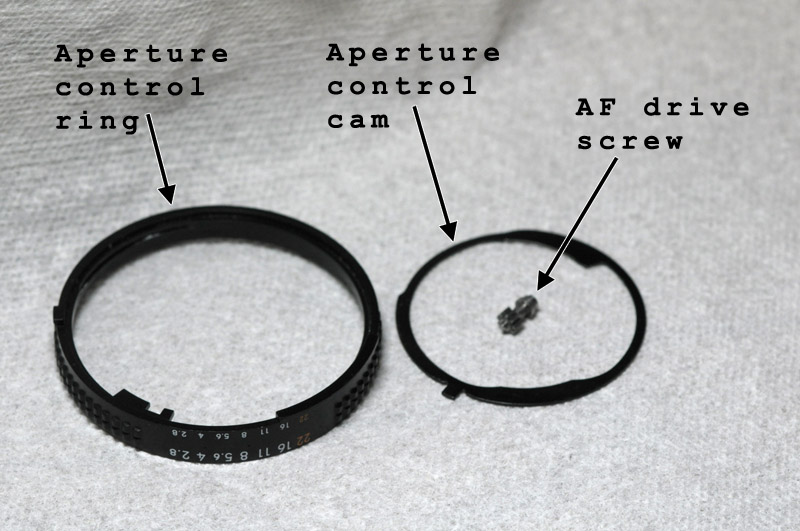
Below, the metal lens lock ring is removed and you can see the aperture control cam and a better look at the AF drive screw. The bottom of the screw is geared which turns the larger gear around the body of the lens for focus. Also visible is the ribbon cable holding the electrical contact plate. Now the aperture control ring can be lifted up. Underneath it is a metal flat spring to act as a detent so while pulling up on the control ring you may feel some resistance.

Here are the aperture control ring and cam and AF drive screw.
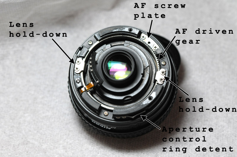
You can see the AF screw plate which the AF drive screw rides on. This can remain in place. Also the large, driven focus gear is visible. The two lens hold-downs actually don’t hold the lens down, they just prevent it from spinning. And the aperture control ring detent is what makes the aperture control ring click at each stop.
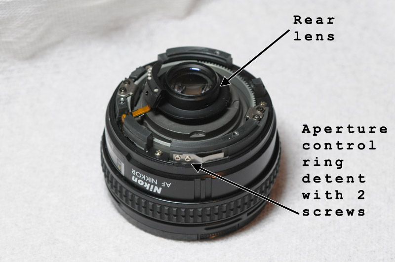
This next step is not necessary to clean the diaphragm, but I did at the time since I was trying to figure things out. So, if you like, you can remove the two very small screws (the smallest on this lens) that hold the detent. If you decide to skip that step then proceed on to the removal of the rear lens. There are two small notches 180 degrees apart on the large metal ring surrounding the lens element. I’m sure there is a spanner for removing this, but I just used some pliers so loosen the element.
The focusing window ring has been removed once the three screws holding it are removed. Again, you don’t need to complete this step. But it does give you a view of the internals. It’s best to leave the focusing window and detent from above in place.
Here is the focusing window ring removed.

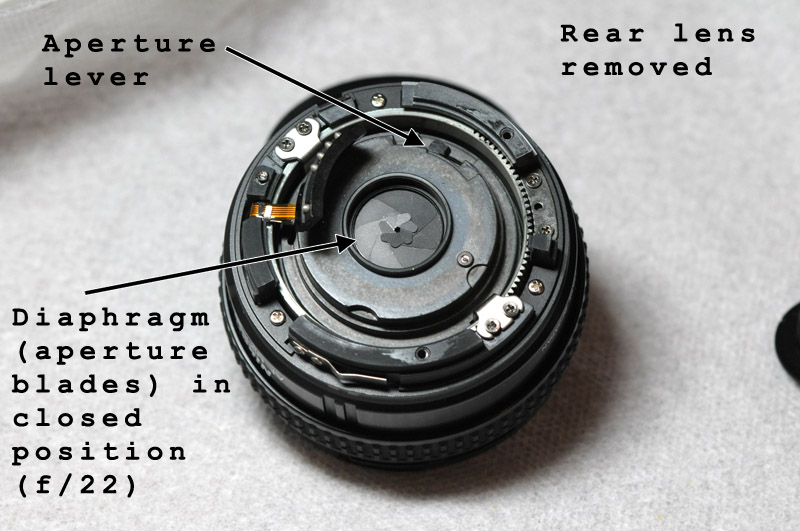
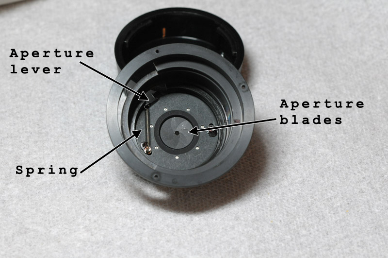
The rear lens has been removed, exposing the diaphragm (aperture blades). The blades are in the f/22 position and if you move the aperture lever, the blades should open. When you release the lever, they should automatically close. When I first took apart the lens, the blades were stuck in the open position. I could manually move the lever but the blades would not automatically close. There is a spring on the other side of the diaphragm (see further below) which controls this action. At this point you could clean the back of the blades, but I would wait until we have access to the other side. So don’t clean anything yet.
Now we move to the front of the lens. The outer plastic ring twists off. You can make a tool using a piece of appropriately sized PVC pipe with rubber on the end for friction to twist the ring off. Or, if you don’t care about dings and scratches you can use my method. I pressed a long wood screw (or any sharp object) into the plastic at an angle and tapped with a hammer to break free. Whatever works for you.

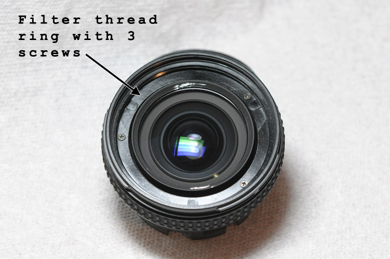
Once the plastic ring is removed, the filter thread ring is exposed with its three screws. Remove the screws and ring. Next remove the main lens element. You can make another PVC/rubber tool for this piece or you can use my brute force method. You can see the two scratch marks in the aluminum ring surrounding the main lens element. This element was tight, but I broke it free using the wood screw and hammer method. Be careful to not slip and scratch the glass.
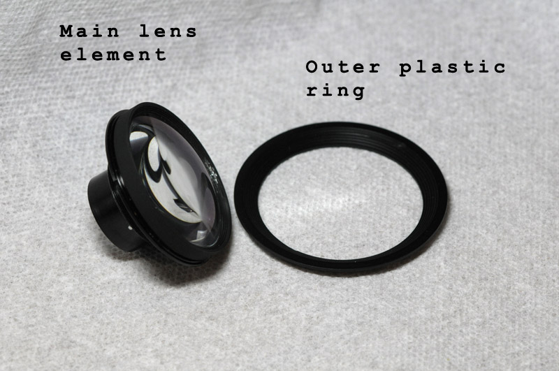
Here are the plastic ring and main lens element.
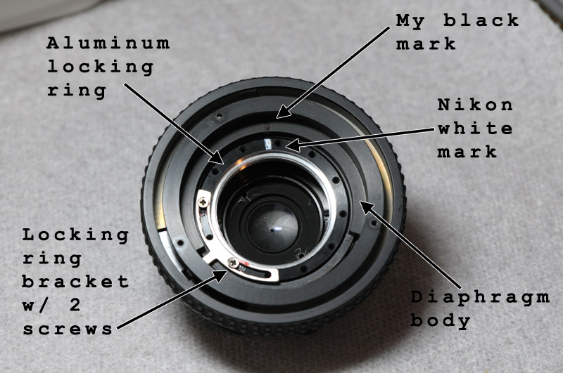
Now this where things get a little complicated. You can see below that the main lens has been removed. You can see the front side of the diaphragm but it’s still blocked by another lens element. Now move the focus to one end or the other. I moved the focus to the near position (opposite of infinity focus). The aluminum locking ring has a white mark on it. Using a black sharpie I put a mark on the ring just outside of the white mark (on the diaphragm body). Also, note which screw holes the bracket is screwed into and note where in the slots of the bracket the screws are. Take a photo if that will help, but the marks are essential.
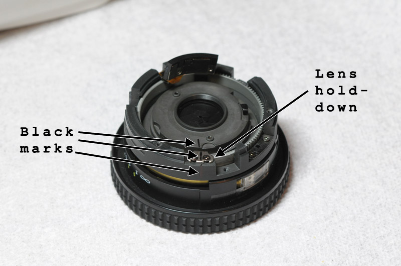
Now flip the lens over and mark one of the two hold-downs. Don’t mark both; mark just one. Make three marks: one on the hold-down, one inside on the diaphragm body and one outside on the outer body. As you will soon see, even with these marks, there will be some guess work and trial and error to get everything back together.
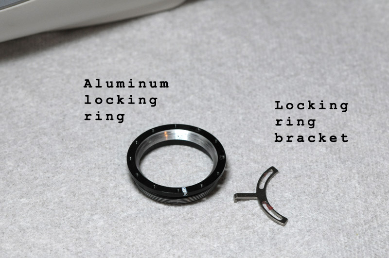
Go back to the front side and remove the two screws holding in the locking ring bracket. Remove the bracket and unscrew the aluminum locking ring. Count how many revolutions you unscrew this because you need to screw it back in to the correct depth as well as line up the marks. You will notice that the protrusion on the bracket has a small foot. This fits in groove on the outer body. Take note of the groove and how the foot fits in it.
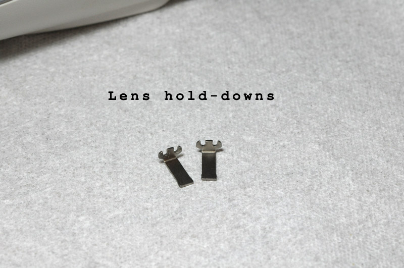
Flip the lens over again and remove the four screws retaining the lens hold-downs (two screws per hold-down). Now you can unscrew the diaphragm body from the outer body.
Once the diaphragm body is unscrewed, we are left with the outer body. You can see the groove I mentioned earlier where the foot for the aluminum locking ring bracket fits.
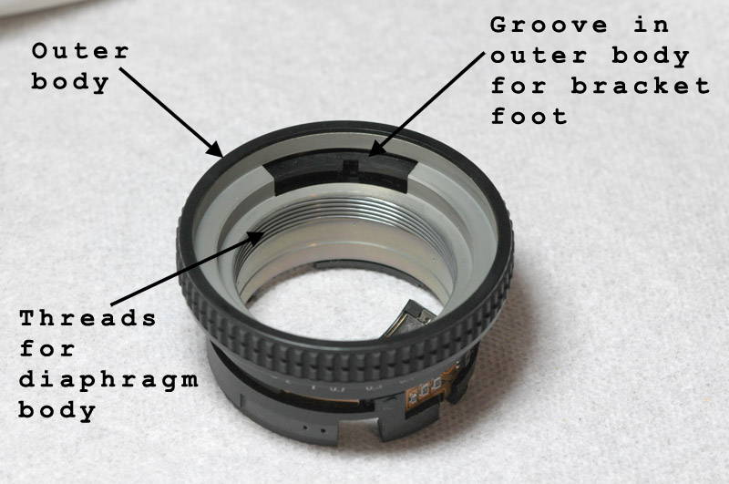
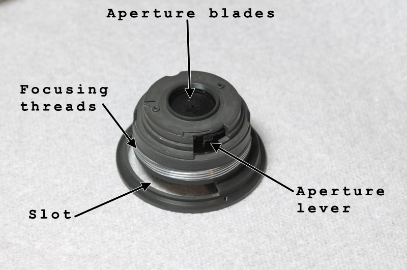
This is the diaphragm body. The slot is where the aluminum locking ring bracket protrusion fits through in order to contact the groove in the outer body.
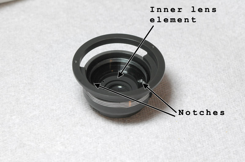
Here is the front side of the diaphragm. We need to remove the inner lens element to access the aperture blades for cleaning. There are two notches where a special made spanner would be used to loosen this element. I used a pair of snap ring pliers. There is a better photo below of the element.
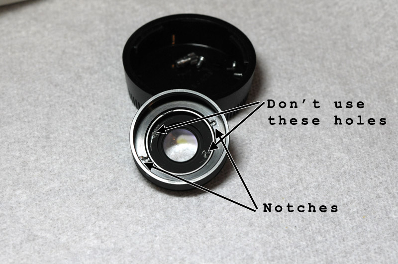
Here is the inner lens element removed with a better view of the notches. Don’t use the other two holes which are used for removing the lens from larger body of the element (which you don’t want to do for this procedure).
The front side of the blades are visible as is the spring which should hold the aperture blades closed. Now it’s time to clean the blades. I used isopropyl alcohol and Q-tips. Move in a clockwise direction to prevent Q-tip fuzz from getting stuck between the blades. I just kept cleaning and rubbing and operating the aperture lever until the blades moved freely and quickly. You can use some compressed air in a bottle to gently dry the area. I’ve read that you can apply a small amount of graphite to the blades to help as dry lubrication. I squirted a puff of graphite onto a tissue and dabbed at it with a Q-tip and then rubbed the Q-tip on the blades (both side). This is to prevent too much graphite from sitting in the area. This did help the blades operate more freely. I suppose the spring could be bad in some cases. That would require a new spring if you could find one or repairing the broken one. The spring feels very flimsy to me and I thought of tightening it up by shortening. Maybe next time I disassemble the lens.
When I reassembled the lens, I found the focusing felt stiff. I supposed the threads between the outer body and the diaphragm body and between the aluminum locking ring and diaphragm body are usually lubricated. I thought about using some grease, but decided to use some anti-seize (Permatex 133A). I used just a trace amount and upon reassembly, the focusing was a lot smoother.
For reassembly, we just reverse the above procedure. Screw the inner lens element into the diaphragm body. Now screw the diaphragm body into the outer body. This is where I came across some difficulty. Usually, when you thread two pieces together they can only start the threading process in one spot. The outer body actually has at least three spots (maybe four…I can’t recall) where the diaphragm body can start to thread. So, you need to choose the correct spot to begin your threading otherwise you won’t be able to fully focus the lens. I first discovered this after first putting the lens together. It would close focus from 0.25m to 0.7m but no further. Next I found I could focus from 0.7m to infinity but not down to 0.25m. So, after some trial and error, I discovered the multiple threads of the outer body. So, now the hard part: you need to thread the diaphragm body correctly into the outer body and thread the aluminum locking ring into the diaphragm body to line up the match marks and so it’s at the correct depth and then attach the locking ring bracket with the two screws while making sure the foot fits into the groove of the outer body. Turn the lens over and install the lens hold-down which was marked and align its marks with the outer body and diaphragm body. If the marks don’t line up then you need to start over and try again. If the marks do line up then install one screw and before proceeding make sure your lens focuses from 0.25m to infinity. If it doesn’t then you need to start over. This is like trying to solve an equation for two variables. It’s tricky and time consuming but if you are patient and methodical then you can get it after a couple of tries. And really, that’s the hardest part of this whole evolution. Once the focus has been confirmed, install the second screw in the hold-down as well as the second hold-down and its screws. Now install the AF drive screw and aperture control ring. Turn the ring to ensure you have good detent actuation. Next, install the aperture control cam and the rear lens. Install the metal lens lock ring ensuring that the aperture lever on the lock ring fits below the aperture lever on the diaphragm. You should be able to move the lever on the lock ring and diaphragm should open and close. Attach the electrical contact plate and install the black ring and the rear portion of the lens is complete. Turn it over and screw in the main lens element, then the filter thread ring and the outer plastic ring. You probably want to clean any lens surfaces before assembling. Also make sure no loose debris is floating around inside. Make sure your screws are tight. And that’s it.
After this procedure, my aperture blades operate freely. However, I now notice softness at the corners of my images which go away when stopped down but something is not right. The lenses are all clean so I suspect the inner lens element is the problem. I loosened it before I realized that it unscrews towards the aperture blades (clockwise to loosen) while it’s still in place so I probably don’t have it adjusted properly. But if you don’t mess with it then you shouldn’t have a problem. However, the problem may be with something else entirely. [UPDATE 1/29/10: I made some adjustments to the bracket on the aluminum locking ring and that fixed the softness. It took a couple of incremental adjustments, but the softness has gone away.] I wasn’t expecting to get the lens apart and back together but I did. And when my 35mm 1:2.0D lens aperture blades start sticking again, I’ll write up another how-to article.
You can contact me if you have any questions or comments or corrections at:
![]()